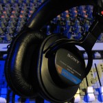
 Recording Magazine sends out a newsletter to its subscribers every few weeks. The newsletter is (coincidentally) titled “Sound Advice” and this month it features a new series on headphones and monitors. I asked permission to reprint this newsletter (and will ask to reprint the others in the series as well) so that those of you with home studios can also benefit from the information. I want to personally thank Brent Heintz, VP/Associate Publisher for granting permission, allowing me to share this great information with you.
Please visit Recording Magazine‘s website and their Facebook Page.
One quick note: I did not reprint the first installment from last month on SOUND4VO because I didn’t feel it had enough information from which the majority of the voiceover community could benefit. Voiceover usually deals with a singular signal (your voice) and therefore it is typically mono. Many of the concepts you will read about in this article are critical for music, because music is typically in stereo (or surround sound). However, the importance of space and spatial recognition cannot be overstated. By their very nature, how you hear headphones and monitors greatly effects how you hear yourself and your ability to interpret what you hear. This article begins to deal with those issues.
So… please enjoy this installment from Recording Magazine’s Sound Advice on Acoustics.
Welcome back to Sound Advice on Acoustics! Last month author Robert Auld presented us with some intriguing problems that seem to have a common solution, if a radical one: What would happen if we elected to do all of our tracking and mixing and mastering with headphones rather than speakers? The answer to that question is a complicated one, and we’re going to spend the next few months taking it apart. Read on!
***
First the bad news: headphones really sound different from loudspeakers. Let us count the ways.
“The principal problem with headphone listening is you have no mixture of left and right channels; they’re piped directly into the respective ears. Because of that it is very hard to judge the width of your stereo stage, the amount of center that you’re getting, as opposed to left and right. You tend to misjudge that on headphones.”
The fancy name for what Jerry is describing is interaural crosstalk. Loudspeakers have lots of it (if your right ear can’t hear the left loudspeaker, something is wrong), but headphones have none. Mr. Bruck continues:
“A sometimes very serious misjudgement on headphones is to think that it’s wetter than it really is. You find on loudspeakers that you are much closer in perspective than you thought you would be listening on phones.”
The reasons for this are a bit complex, but they probably have a lot to do with aural masking—that is, with the tendency of one sound to mask another. In this case we are dealing with direct sound (a lead vocal, for instance) and reflected sound (as in the reverberation stimulated by that vocal). To quote another authority:
“Angular separation between direct and reflected sounds has a minor effect on the audibility of the reflections, except when the two are coincident, when the reflection tends to be masked by the direct signal.” —Ron Streicher and F. Alton Everest, The New Stereo SoundBook, 2nd edition.
In other words, if the reverb is coming from the same direction as the vocal or very close to it, it will tend to be masked by the direct sound. Here is how I think this applies to the headphones vs. speakers question.
With typical stereo loudspeaker monitoring the angle between speakers is about 60 degrees, or 30 degrees to each side of our listening position. This is a small portion of the 360 degrees over which we hear. It is safe to say most of the sound approaches from in front of us.
With headphones the earcups encompass an angle of 180 degrees relative to our ears, equivalent to speakers placed 90 degrees to each side. This is a big change, and it allows for greater angular separation between at least some of the direct and reflected sounds in a recording. A portion of the reverberation will literally be unmasked, and so the recording will sound subjectively wetter.
Experimental data on angular separation and masking imply that this difference is equivalent to increasing the reflected sound level by 5–10 dB. This would certainly be an audible difference, and it bears out Jerry Bruck’s observation (and my own experience). But there is one circumstance where “it sounds wetter on headphones” does not apply. This is when you are making a binaural or quasi-binaural recording.
In its purest form, binaural recording uses small-diaphragm microphones placed in the ears of an anatomically correct dummy or, less conveniently, in the ears of a real person. Then there are quasi- binaural microphone arrays like the Crown SASS that mimic the ear spacing and acoustic shadowing effects of the human head.
In either case, recordings made with these systems and reproduced with headphones preserve the spatial cues of the recording environment with considerable accuracy. This allows our brain to sort out the direct and reflected sound as it does in real life, with a gain in realism and clarity that can be really startling.
When you play the same binaural recording over loudspeakers the spatial cues are altered. What had been all around you is now placed in front of you, as if viewed through an open window, and—masking effects or not—it tends to sound more distant.
This is, of course, a special case, as most recordings use conventional microphone arrays that do not preserve spatial cues accurately, regardless of the playback method. So lacking a realistic acoustic model to work with, our brain resorts to other methods of analysis, and things like masking effects assume greater importance.
So far we’ve learned that headphones create a weird stereo image and do strange things to reverberation. What else have we got to look forward to from our potential critical monitors? Let’s have Jerry Bruck talk about low frequencies:
“Low frequencies are only partially a question of what you are hearing with your ears. A lot of it is, in fact, called “skin effect,” borrowing a term from another discipline. No matter what the frequency response of the headphones turns out to be, no headphone ever gives you the sense of low frequencies that you get from speakers.” This is why Hollywood doesn’t use headphones when it wants to make you feel an earthquake or an explosion.
If headphones differ from loudspeakers in such significant ways, can we still use them as critical monitors? The answer, I think, is “Yes, but…” Starting next time, we’ll look at the advantages that might make us say “Yes”, and then follow up with the “buts”. See you then!
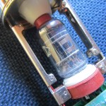 Questions about tube microphones come up often. So many people in the voiceover and recording industries are in search of a certain, often elusive sound, that most people describe as “warm”. For some, tube microphones are the answer. “Tubes” refer to vacuum tubes. Vacuum tubes are similar to light bulbs, but designed to regulate, or control the flow of an electrical signal .
 There is a lot of talk about mic modelers in social media today. A while back, I was asked the question in regards to

